
Here is a good article on 6m dipole.
ALL credit for this goes to Kevin Loughin . Watch his video at https://www.youtube.com/watch?v=fBdcyQvu3jM
http://kb9rlw.blogspot.com/2021/03/a-6-meter-cage-dipole-using-window-line.html
It’s springtime here, that time of year where 6 meters occasionally opens up. And I need a decent 6 meter antenna. I’d love a beam, but I live in an RV and have very limited space. So a dipole it is.
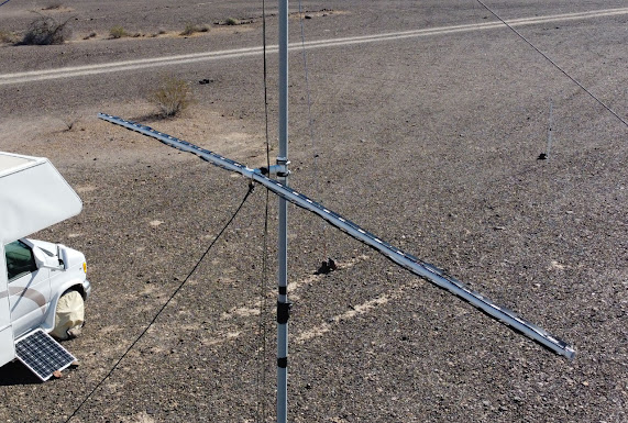
I’ve long been aware of cage dipoles and their broader bandwidth verses a regular dipole. So I thought up a way to make a simple four wire cage dipole for 50 MHz. Here is the design.

(Click on image for full size, then right-click on it to download.)
In order to test the increase in bandwidth, I initially just put a singe wire on each leg and swept it with my Blue VNA.
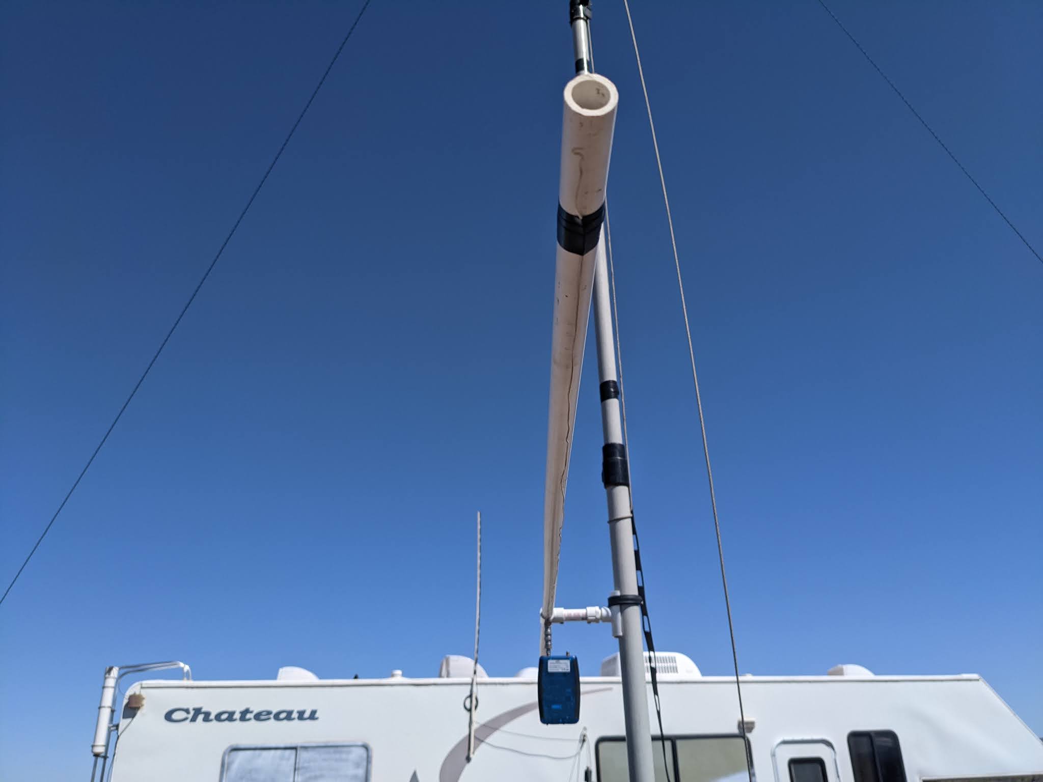
(single wire dipole being measured)
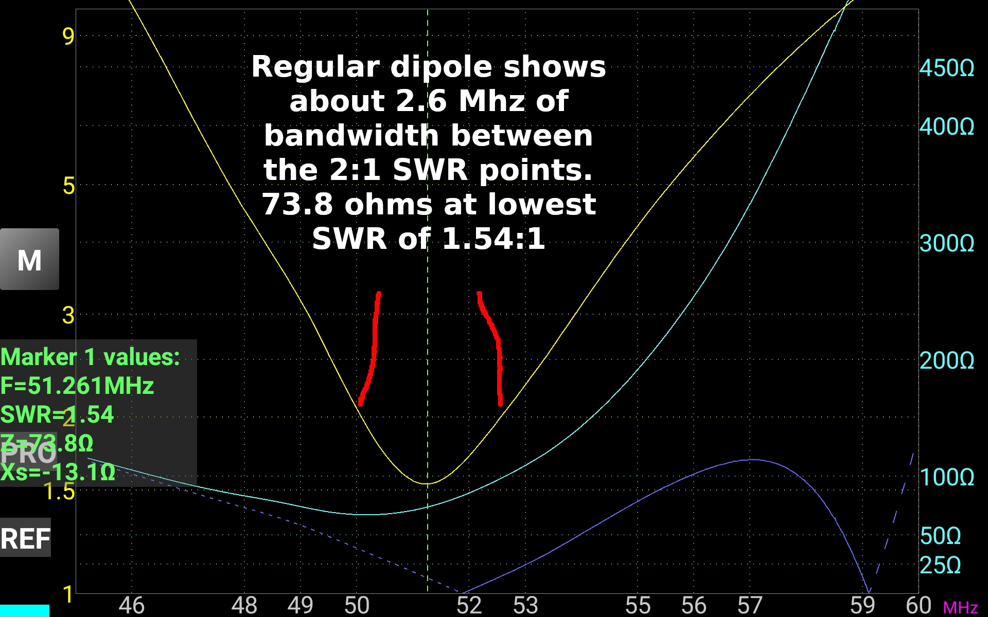
And here is the sweep of the single wire dipole, showing a bandwidth of 2.6 MHz between the 2:1 points. One interesting point I noticed. Modeling and literature all point out that a half wave resonant dipole will have ~74 ohms impedance at it’s resonant frequency. We measured 73.8 ohms, how about that!
Then I finished building the cage and swept it again.
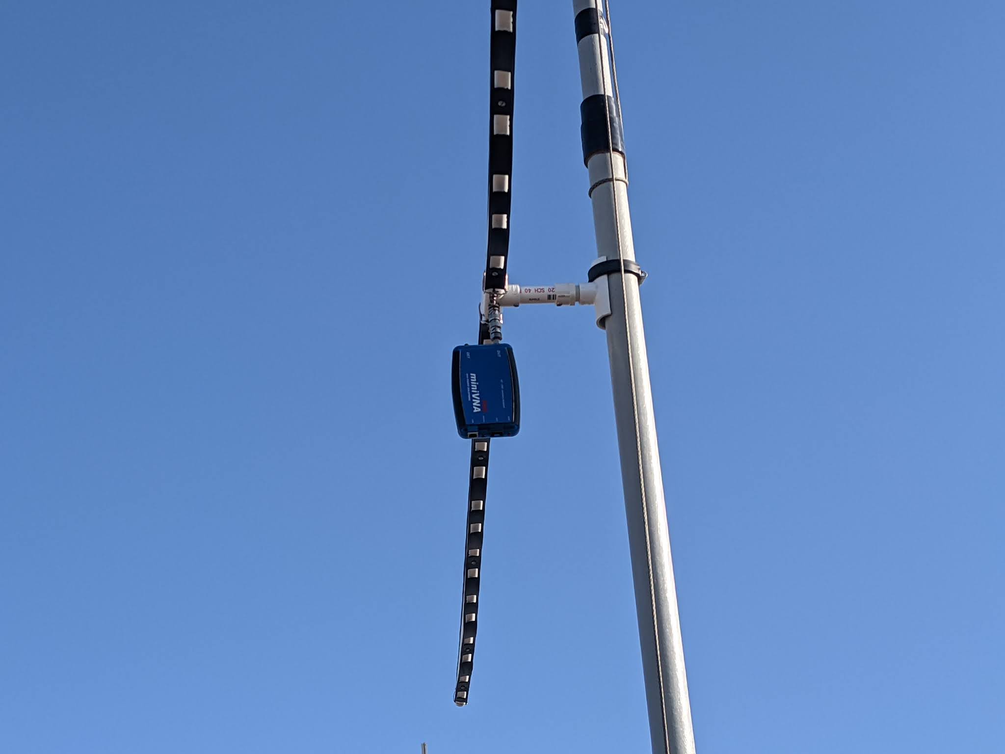
(The cage version being measured.)
Here’s the result. The bandwidth has increased by 77% to 4.6 MHz!

So there we go. The cage design not only increased bandwidth, but also slightly lowered the impedance and SWR at it’s lowest point. Some might wonder why I didn’t trim the antenna to raise the lowest SWR to the center of the band. Well, 99% of my operation on 6 meters is down at the CW/SSB/digital end of the band, so that’s where I wanted the lowest SWR.
Now I’m all ready for those coming 6 meter openings.